
Restoring an Abused and Neglected Gibson GA19 RVT Falcon Guitar Tube Amp
Restoring an Abused and Neglected Gibson GA19 RVT Falcon Guitar Tube Amp
All rights reserved 2016
By Howard Rose of Commercial Audio Systems in Chicopee MA
I've been tinkering with electronics most of my life. Starting young, I destroyed my first bit of test equipment before entering high school. Those youthful experiments taught me that AC and DC don't get along well.
What followed was a fascination with electricity, radio, stereo, sound reinforcement, audio recording, and instrument amplification. I'm self taught, but I've had some great mentors (many thanks to Thomas Edison, Nikola Tesla, Leo Fender, Jim Marshall, the RCA tube manual, Western Electric publications, Gerald Weber, J. Scott McArthur, Jim Skiathitis, and my Dad who bought me my first crystal radio kit.) What was once a hobby has become a rewarding part of my career.
Having said all that, I probably shouldn't be writing this article.

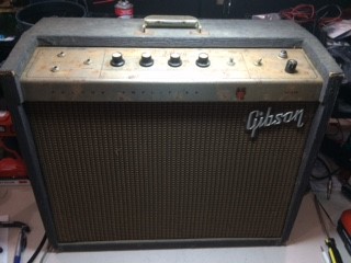
Once upon a time this Gibson GA19 RVT Falcon was someone's favorite. Now, it was filthy, badly rusted, full of cobwebs and mold, and many corroded parts. The thought of anyone plugging it into a wall socket was terrifying. Most reasonable people would have junked it without a second thought.
My colleague gave me a short history. The owner had relegated it to a barn in the back yard where it was forgotten for years, and then rediscovered only to learn it was no longer useable. The amp was delivered to his shop with the request to bring it back to life for short money, if possible. His schedule was full and the Falcon landed on my work bench.
As with all my repair projects, I like to get to know the patient as much as I can.
The first thing I learned was that the supplied schematic was the wrong version. I didn't remember multiple incarnations of the GA19, so my curiosity was peaked. As it turns out there was a “tweed” model in the late 1950's and early 1960's, followed by a short-lived rough tolex covered cabinet. The Crestline series Falcon made its debut around 1963. By the mid 1960's, Gibson had reworked it as a solid state amplifier.
My document showed V1 and V3 were 6EU7 preamp tubes. V2 was a 7199 intended for the reverb drive and recovery. V4 was another 6EU7 set up as a final gain stage and phase inverter.
The output tubes were 6V6 models. The rectification was accomplished through a 5Y3 tube .
This amp was different:
V1;6EU7
V2;6C4
V3;6EU7
V4;6EU7
V5 6V6
V6 6V6
V7 5Y3

The initial research of the internet was not helpful. What I had was a transitional amplifier with some aspects of the Crestline series, but with elements of an earlier build. In fact, Gibson had marketed a similar product under their Maestro brand as the M-216RVT. This is neither unusual nor unique to Gibson.
Having spent many months rebuilding a Scott 299 series home stereo amplifier, I learned first hand that significant, undocumented engineering changes are the rule rather than the exception. In the case of the 299 project, the power supply schematic and voltage measurements bore little resemblance to what I found in the chassis.
Further, experience has shown that manufacturers will start with a baseline model, and add options to flesh out their product line. As case in point would be Fender's AB763 series. This basic preamp design has served as the foundation of the “Blackface” Bandmaster, Deluxe, Super Reverb, Twin Reverb, Showman, Dual Showman and others.
The Scott rebuild was valuable in that the research led me to Black Magic Amplifiers, a UK based electronics vendor with an expansive library of schematics. Their web site is a great resource, and they should be commended for publishing it (http://www.bmamps.com/Tech_sch.html). There, I found an earlier circuit diagram of the Falcon that was more like the one I had. This better illustrated the filtering circuit, and provided an accurate description of the signal path.
The new information made it clear that previous attempts to service the Gibson had been poorly realized. Badly chosen components, some of them literally wire-tied to others, bare wire exposed to potential grounding points, electrolytic caps with the ground wire hacked off, and still in the circuit....yipes!
The rebuild began by removing anything that had to do with the power supply. All electrolytics connected to the DC high voltage secondary were clipped out, measured for function (Fluke Model 117 capacitance tester), and replaced as required. Ultimately I re-installed an exsisting 20uf 450 volt capacitor for the B+ circuit, and mounted it in the chassis between a pair of three lug Barrier Strips. The middle lug became a useful grounding point. The dropping resistor to the Screen grid was attached to the second three lug strip, and a new 10uf 450 volt radial capacitor was installed, negative to the middle lug. Wiring to the the main circuit assembly (a very clever design by the way; see the photo above) was re-established. The remaining electrolytics were located on the opposite side of the chassis near the preamp tubes. There is very little space in this part of the chassis, Again, a barrier strip was installed, along with two 10uf 450 volt radial electrolytics. These were attached to the first stages as per the circuit diagram.
A thorough inspection of the internal mechanics and circuitry was performed. At this point I felt confident that a slow power-up test was in order.
I was concerned about the tube complement and vendor sources before a more careful inspection proved that I would not have to find a 7199 valve. This was a big relief. They are no longer common, and can be very expensive. It is also an oddball: half triode and half pentode. I had worked on an Ampeg Gemini II several years ago, and it employed one in the phase inverter section. Luckily, I discovered that a 6U8 series tube could be substituted, if the socket was rewired (Note: other possibilities include the 6AN8, 6GH8, and 6BG8). The client agreed with this modification, and it has worked well ever since. However, I didn't look forward to repeating the adventure in an amp with limited working space and poorly maintained components.
Instead I needed a 6C4, and also thought the 6EU7's should be replaced after testing them on my EICO 666 tube tester. However, I was up against a budget and the preamp tubes would have to wait. I knew I could go to the internet and find something, but I haven't always had good luck with this approach. I do have the advantage of being located near Viva Tubes in Chicopee, Massachusetts. A client suggested I introduce myself to them after I completed a repair for him at my shop. So I called, made an appointment, and spent an hour or so talking shop and comparing experiences. They had a solid 6C4 that completed the project, and I've been going back ever since.
The final testing of the amplifier was done in stages, first with no tubes and an 8 ohm, 100 watt dummy load on the output transformer. I also attached my oscilloscope to the output in order to monitor the wave form. An EICO 1078 variac slowly brought up AC voltage to 120 VAC while I carefully watched the ammeter. The power transformer showed acceptable voltages on all secondaries. Next, the 5Y3 rectifier and preamp tubes were installed, and the process repeated. Filaments measured at 6.3 volts AC, and plate voltages were OK as well. Finally, the power tubes were replaced and the variac was used to gradually bring the amp up to operating voltages. I let it sit for a while with the controls at minimum. Measurements again showed the components to be within tolerance. A sine wave signal generator was connected to the first input at 800 Hz, and level was brought up slowly.
It worked.
A swept signal on the oscilloscope showed that the Gibson was back in action.The chassis was re-installed in the now cleaned and vacuumed cabinet, and the original speaker was reattached.
My reading suggested that this amplifier was voiced for humbucker style pickup instruments. More than once it was noted that single coil guitars sounded thin at best, and at worst lethal through the Falcon. This GA19 had been modified in several ways, including the removal of a notorious filter network in between the gain stages. I found that instruments with either type of pickup were quite usable depending on input choice, and tone and volume settings. Even the reverb and tremolo sounded great.
Happy customer, satisfied technician.